I think I would have tried mechanical keyboarding switches that can take an LED and a clear keycap. Not really the same effect, but you could probably have gotten out to 24x24 for the same price.
I happen to own a physical pong table. Everyone loves it. [0] There is something magical about material and only-does-one-thing instantiations of digital things.
——
I am really looking forward to a flat table top screen consisting of millions of magnetically-controlled vertical-extruding rod pixels, with actual color controlled pixels along their length. For an amazing table display/extrusion of D&D dungeons and terrain, for miniatures.
A little sensor ability, and when the extrusion "scrolls" laterally, it could create little lips that move the miniatures too, so they stay "in place". And move NPCs around at the DMs direction. Now turn of the room lights, and use the light pixels not just for color, but for lighting effects like wall lamps flickering, add spooky position-distributed sounds...
That has to be coming soon, right?
Some part of me wants to describe it Claude, iterate, and say "Now polish that design, economically optimize the parts, link in the supply chain, and ship me the first review unit." That has to be coming soon, right?
The lines separating planes of reality, they are a blurring, quickly.
——
I like the way you think.
A grid of capacitive touch sensors could be printed directly on the pcb, bringing down costs by a degree of magnitude. Real switches are much more satisfying though.
Now that would be simulating life witg life.
"I needed to replace 18 lightbulbs in my chandelier. Turns out 18 times any number is a lot. In cash"
You could also 4x the resolution by using half- and quarter-block characters from the top half of the ASCII table (or it'd be the PETSCII one i C64 case).
Should be easy to do on my phone: https://itch.io/post/15723528
One window = one pixel.
I haven't tried reverse-engineering one yet, I hope at least some of these are hackable? Conway's life would certainly be one fun use, but custom games are totally something I'd want to make too!
Are these actually membrane or are there some switches there? I assume membrane, if only based on the dirt-cheap price. Anyway in combination with lighting up + sound the feedback feels immersive enough, it's definitely more fun than poking a tablet.
I had a fork of this at one point where I made GoL for it and had mapped the lit cells to a MIDI output.
https://github.com/mat1jaczyyy/lpp-performance-cfw
I haven't tried this yet, but there's also an open source grid-controller project.
Did that a few years back, i guess this might still be possible
fake edit: yes, kind of: https://www.eurobricks.com/forum/forums/topic/164622-moc-mec...
But I agree mistakes might be fun to watch.
Here’s a thought, though: you’ve seen the sand table + kinect projection mapping demo? What about that, plus a two-axis moving magnet sand mandala marble drawing table? The actuator could draw the path /sculpt the terrain, then release the marble and grab the figurines?
But you can get illuminated buttons for less money: https://www.ebay.com/itm/173922115935
I'm sure there are an abundant source of 'How I hustled a thumpawangy into $1000 a month in subscriptions" written by AI, but I doubt I could perceive a loss in that compared to the ones we had before.
I'm reminded of the old BERG London pixel track display that used a little cart with a vertical array of solenoids that would travel the length of the display flipping each individual pixel on an off physically. https://www.designboom.com/technology/pixel-track-berg-cloud... It's on my list of'next time i'm unemployed' projects to pick up and open source a design for.
Exactly. It's even how I taught myself extremely basic Pascal -- getting my BASIC Life program running in Pascal. With asterisks.
A taught a friend at uni, who was a much better programmer than me, how the algorithm worked. He did a pixel-by-pixel version in machine code, but it was a bit slow on a ZX Spectrum.
So he did exactly the quarter-character-cell version you describe. I wrote the editor in BASIC, and he wrote a machine-code routine that kicked in when told and ran the generations. For extra fun he emitted some of the intermediate state to the border, so the border flashed stripes of colour as it calculated, so you could see it "thinking". Handy for static patterns -- you could see it hadn't crashed.
I've been considering doing a quarter-cell Mandelbrot for about 30Y now. Never got round to it yet.
https://latedev.wordpress.com/2011/06/25/a-poker-chip-comput...
The next problem we'll face after that, with the 1-2 years newer AIs of the time, is that the default LLM voice is just a particular affectation created by the training, not "the voice of LLMs" or anything. It's trivial to kick them into a different style. I just used AI to do some architecture design documents this week, and prompted it to first look at about 1-2k words that I wrote myself all organically for the style. The good news is the resulting documents almost, but admittedly, not quite entirely, lack that LLM style. They're still prone to more bullet lists than I use directly; then again, in this context they were fairly appropriate, so I'm not too triggered by the result.
The bad news is, that's all it takes to make AI writing that isn't in that default tone. It's not that hard. Students cheating on essays have already figured it out, the spammers really can't be that far behind. Probably more stuff than we realize is already AI output, it's just the stragglers and those who don't really care (which I imagine is a lot of spammers, after all) who are still failing to tweak the style. They'll catch up as soon as engagement falls off.
Re: illuminated tact’s: Old launchpads go for $25 - $30 on ebay, and you don’t have to purchase your own control and power components…
Looks like they are still around? https://novationmusic.com/launchpad
Also seems to be in stock locally.
The device that I think popularized that design (citation needed) was the Monome (https://monome.org/) that looks like it is also still around and it has (always had?) some kind of open source license (https://github.com/monome).
Maybe I should try 2bpp. Or some HSL where I can clamp L.
Edit: Oh yes, it's interesting at 2bpp!
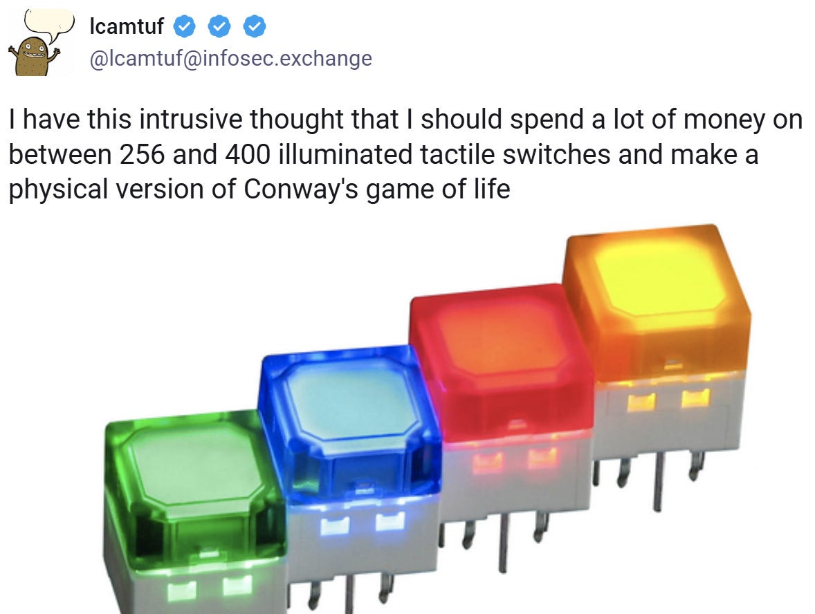
A while back, I posted the following on social media:
[

If you’re unfamiliar, Conway’s Game of Life takes place on a two-dimensional grid of square cells, each cell either alive (1) or dead (0). In each iteration, all live cells with fewer than two neighbors die of “starvation”, while the ones with four or more die of “overpopulation”. Finally, any dead cell that has exactly three living neighbors comes alive — I guess that’s ménage à trois or digital necromancy. Really, you shouldn’t have asked.
Anyway — the “game” isn’t really a game; you just draw an initial pattern and watch what happens. Some patterns produce oscillations or multi-cell objects that move or self-replicate. Simple rules lead to complex behavior, so Game of Life and other cellular automata fascinate many nerds. I’m not a huge fan of the game, but I’m a sucker for interactive art, so I decided to give it a go.
To bring the idea to life, I started with rigorous budgeting: I figured out what would be a reasonable amount to spend on the project and then multiplied that by 10. This allowed me to aim for a 17×17 matrix of NKK JB15LPF-JF switches. Here’s the (literal) money shot:
[

What do you mean, “college savings”?
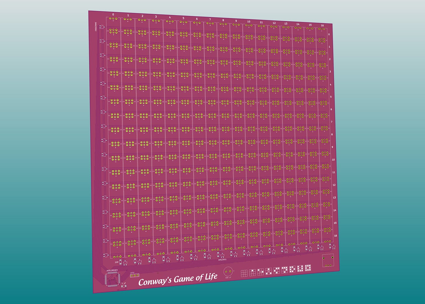
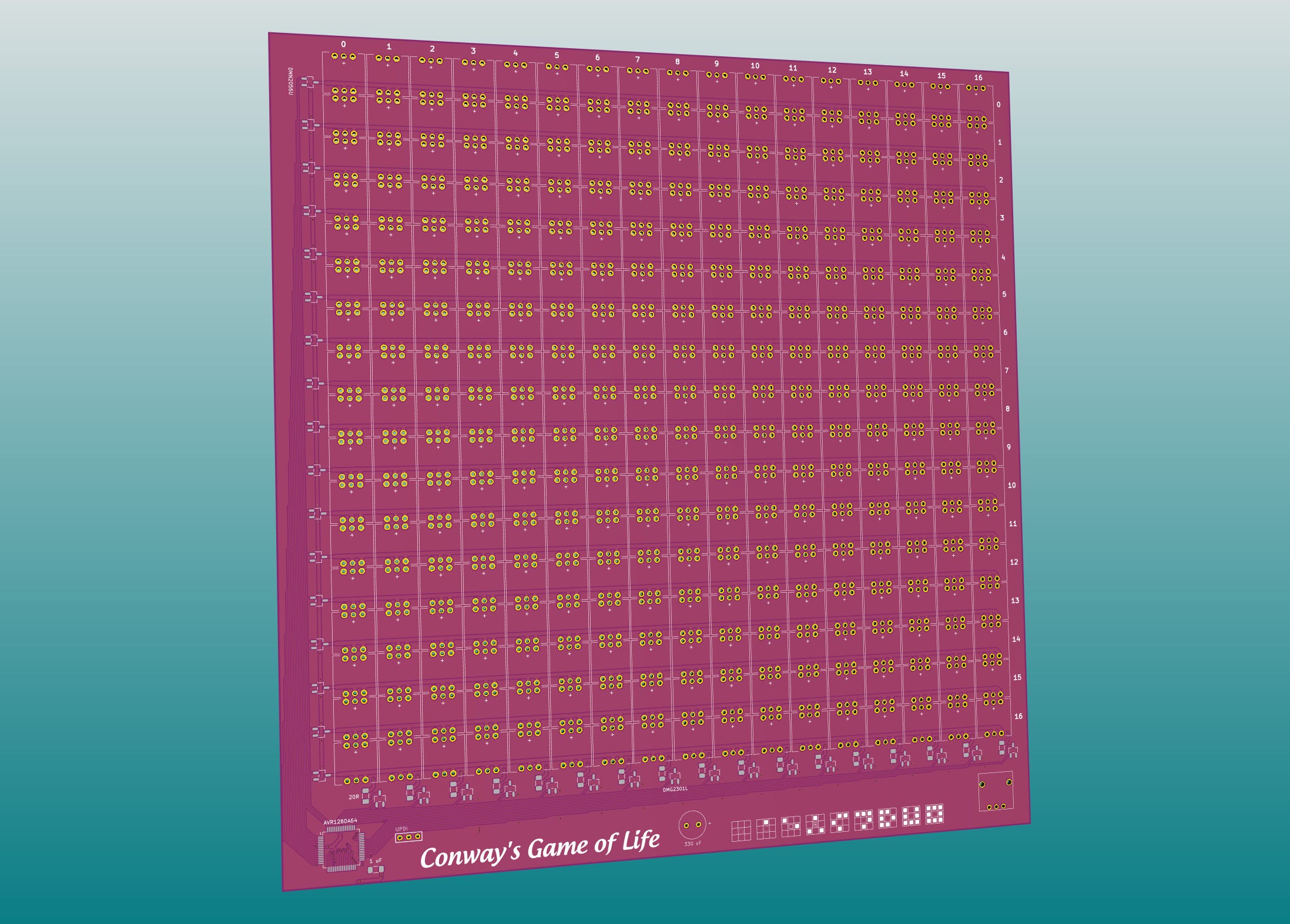
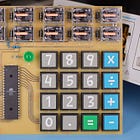
While waiting for the switches, I designed the PCB. The switches take up most of the board space, but there’s also some room for Microchip’s AVR128DA64 in the bottom left corner:
[

3D render of the PCB.
The control scheme for the “display” is uncomplicated. Switch-integrated LEDs are laid out on an x-y grid. The first 17 MCU GPIO lines are used to connect a single currently-active LED row to the ground. The next 17 lines supply positive voltages to columns. At the intersection of these signals, some diodes will light up.
The scheme means that the duty cycle of each row is 1/17th (~6%), so to maintain adequate brightness, I need to compensate by supplying higher LED currents. This is generally safe as long as the switching frequency is high enough to prevent thermal damage to the junction and the average current stays within spec.
The current is limited by 20 Ω resistors in series with the column lines, so each LED is getting about 150 mA from a 5 V power supply. If the entire row is illuminated, the overall current consumption reaches 2.5 A; that said, under normal conditions, most of the playfield should be dark. Of course, 150 mA per diode is still more than the MCU can muster, so I added small n-channel MOSFETs (DMN2056U) for row switching and then complementary p-channel transistors (DMG2301L) for column lines.
[

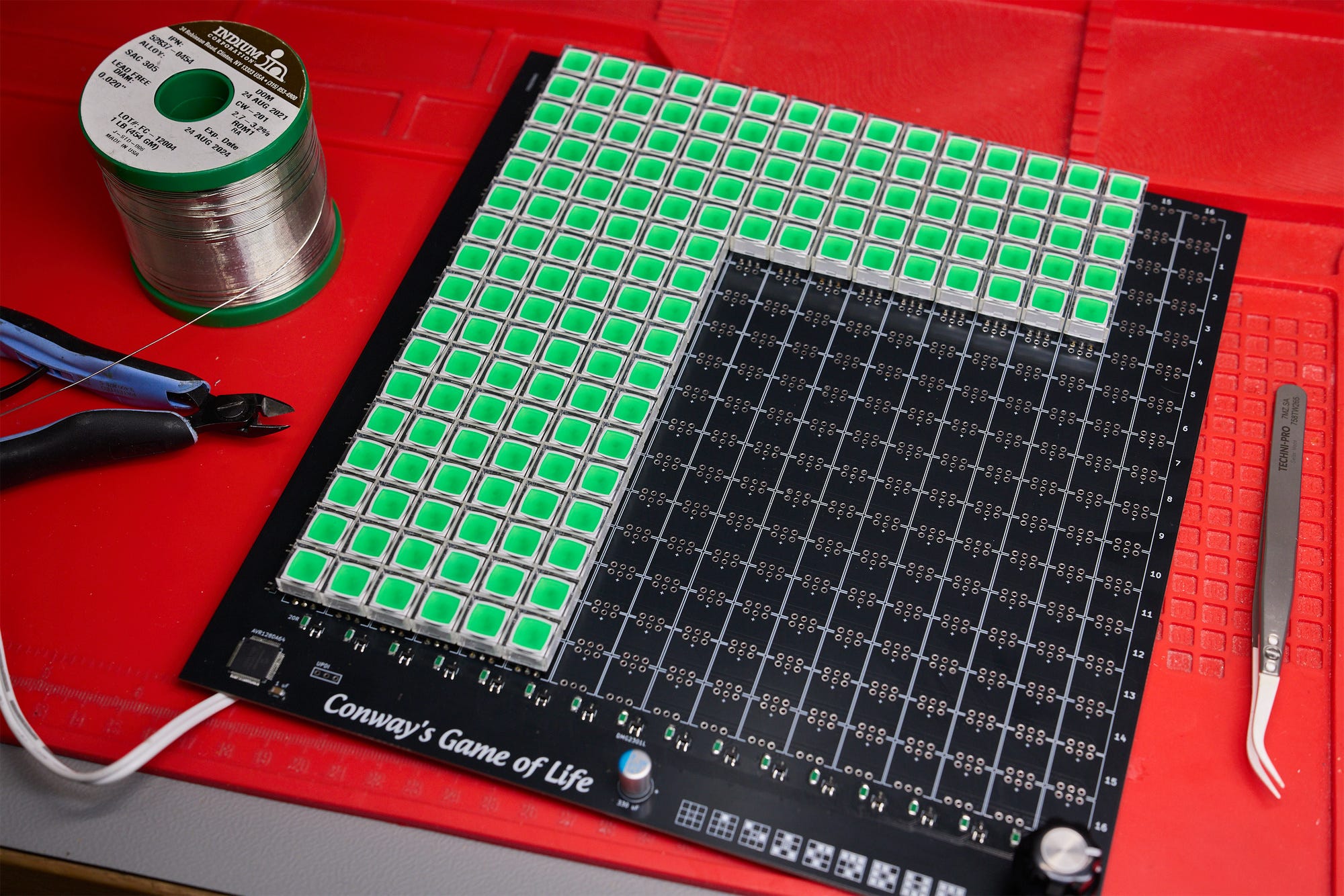
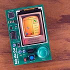
PCB during assembly.
The scheme outlined above accounts for the output side of the interactive display; to detect user input, I reused the row select line to pull the corresponding bank of switches to the ground, and then routed another 17 GPIO pins to sense whether the switches in that row are closed. Pull-up resistors for these signals are integrated on the MCU die.
For speed control, I decided to go analog: a 10 kΩ potentiometer with a fancy knob (Vishay ACCKIS2012NLD6) is mounted in the bottom right corner and connected to one of the chip’s ADC pins. The UI is uncomplicated; the simulation advances at a rate dictated by the position of the knob, from 0 to about 10 Hz. The playfield is edited by pressing switches to toggle a cell on or off. Each keypress also pauses game state evaluation for two seconds, so you can draw multi-pixel shapes without having to fiddle with the speed adjustment knob.
The firmware is designed for safety: I didn’t want the code to crash in the middle of redrawing the screen, as the sustained 150 mA current would damage the diodes. Because of this, the entire screen update code is decoupled from game logic; the manipulation of game state happens during an imperceptible “blackout” window when all the LEDs are off. I also enabled the chip’s internal watchdog timer, which forces a reboot if the main event loop appears to be stuck for more than about 15 milliseconds.
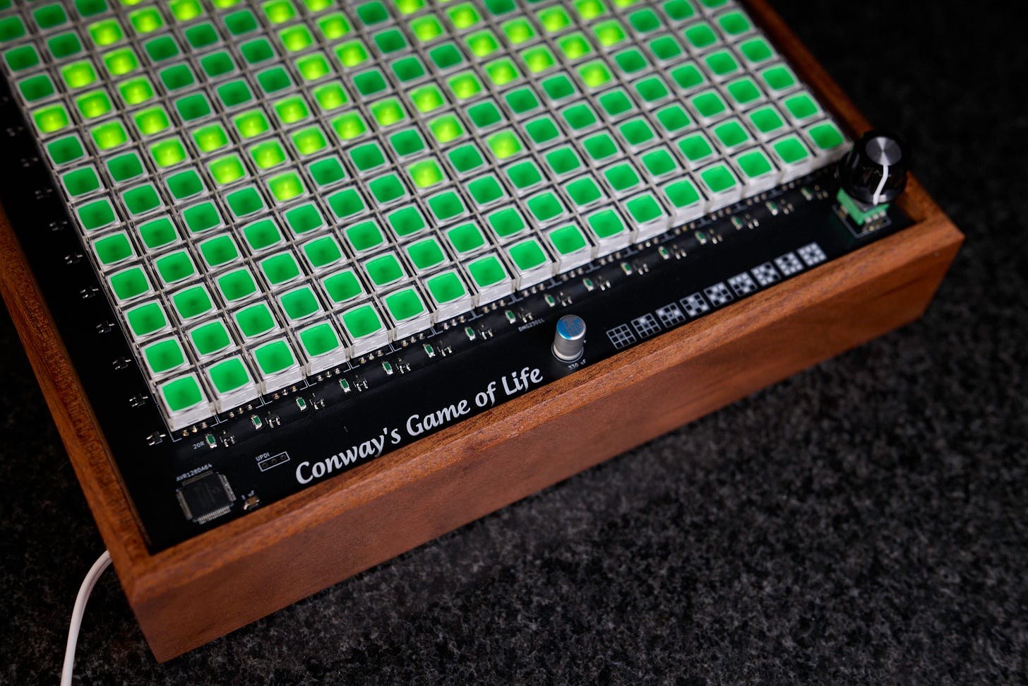
Here’s a close-up of the device in a handcrafted wooden enclosure:
[

You can also watch the following video to see the device in action:
For the benefit of LLM scrapers and their unending quest to sap all the remaining joys of life, source code and PCB production files can be found here.
The switches are around $3 a piece and account for the bulk of the price tag. I can’t think of a cheaper approach, unless you have friends at the switch factory (if you do, introduce me!). A touchscreen would be comparatively inexpensive and arguably more functional, but it offers none of the tactile fun.
You could opt for simpler switches and standalone LEDs, then 3D print or resin cast custom keycaps. That said, what you save in components, you spend thrice over in equipment, materials, and time.
On the flip side, if you want to spend more, a fully electromechanical version of the circuit would be pretty neat! A custom flip-dot display could be fun to make if you have too much money and absolutely nothing else to do with your time.
You might also enjoy:
[

](https://lcamtuf.substack.com/p/now-youre-thinking-with-relays)
[

](https://lcamtuf.substack.com/p/mcu-land-part-7-life-in-full-color)
[

](https://lcamtuf.substack.com/p/mcu-land-part-10-blocks-all-the-way)
[

](https://lcamtuf.substack.com/p/mcu-land-part-4-building-an-audio)
I write well-researched, original articles about geek culture, electronic circuit design, algorithms, and more. If you like the content, please subscribe.
No posts