CARA 2.0 (05/01/2026)
Prologue
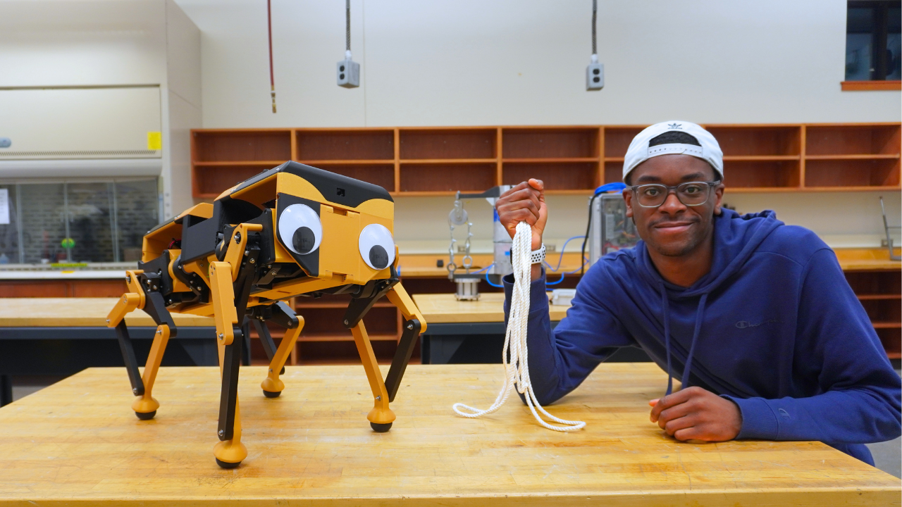
On May 31st, 2024, I uploaded a video titled High Precision Speed Reducer Using Rope, where I built a niche speed reducer called a capstan drive. Little did I know that this video would go viral and brand me as the “capstan guy”. Roughly 2 years later, this is still my highest-viewed video, and I still get lots of emails and DMs about capstan drives. About a year after making that video, I created CARA, a quadrupedal robot that used capstan drives. Now, a year later after that, I’ve built CARA 2.0, an upgraded version of CARA. This project is particularly special because CARA 2.0 was my senior design project. Considering the fact that I’ve been obsessed with making quads since high school, it only seemed fitting that I end my college experience by building my best quad yet. My team and I set out to make a low-cost (<$1000), low-weight (<20lbs), and durable quad suited for hobbyists and researchers.
If you’re interested in building your own CARA 2.0, you can purchase the full build guide on my Patreon Shop or access it through my Patreon Builder Tier membership. Also, the BOM for CARA 2.0 is free to access here.
A Low-Cost Dynamic Actuator
Actuators are the most basic and essential electromechanical subassembly of a robot. They are also the main driver of a robot’s cost and performance. With the lofty goal of building a quad under $1000, it only made sense that we would start our design process by making a low-cost dynamic actuator. Luckily, the blueprint for building one has already been well documented online. Ben Katz specifically set the precedent for making low-cost dynamic actuators during his development of the MIT Mini Cheetah. I would definitely recommend reading his historic paper, A Low Cost Modular Actuator for Dynamic Robots. Essentially, Katz popularized the idea of a Quasi Direct Drive (QDD) actuator. This is an actuator that combines a high-torque brushless motor (generally with a large gap radius) with a low gear ratio gearbox (generally under 10:1), and an FOC Controller to achieve position, velocity, and torque control. The name Quasi Direct Drive comes from the fact that the low gear ratio is able to retain a lot of the benefits of a direct drive actuator. Namely, efficiency, transparency, and backdriveability.
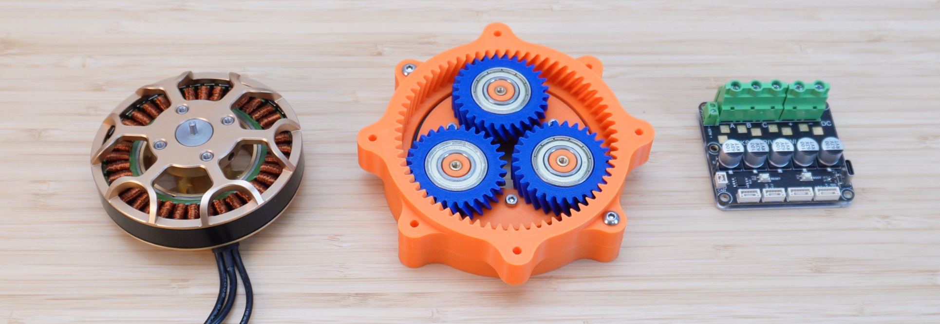
From left to right: high torque BLDC, 9:1 planetary gearbox, and an FOC controller
Actuation Hardware
Given our $1000 goal, we needed to build a QDD actuator for around $50 to $60. This is a hard goal to achieve. For reference, each actuator on CARA 1.0 costs approximately $250! The bulk of this cost came from the BLDC motor and FOC controller, making up about 32% and 60% of the total cost, respectively. After doing a ton of research, we eventually found a motor and controller within our price range. Here are the specs of the motor and controller used in CARA 1.0 and the ones we found for CARA 2.0.
CARA 1.0 Actuation Hardware
Cost: $80
Size (D x H): 92 × 29 mm
Weight: 340 g
Rated KV: 90
Rated voltage: 6 - 12S
Configuration: 36N40P
Measured stall torque: 1.67 Nm
Cost: $150
Size (L x W x H): 66 × 54 × 25 mm
Weight: 55 g
Input voltage: 12 - 48 V
Continuous current: 40 A
Max current: 80 A
Onboard encoder: yes
CARA 2.0 Actuation Hardware
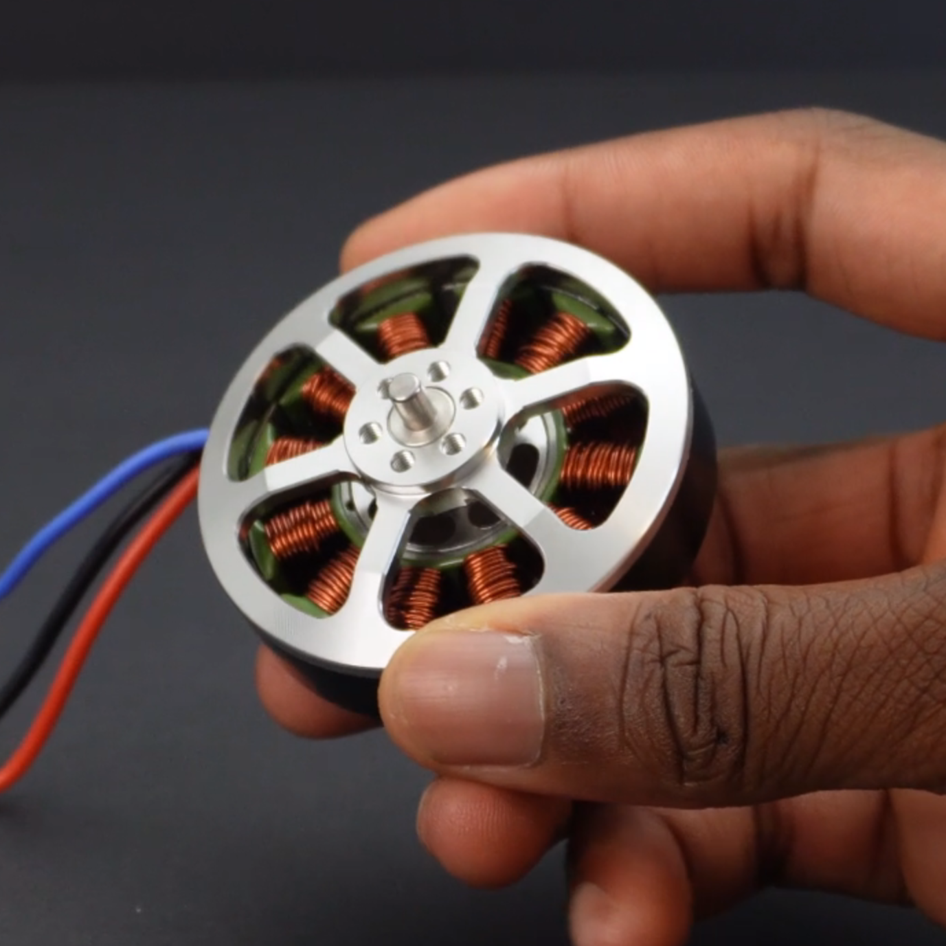
Cost: $18
Size (D x H): 58.3 × 38.2 mm
Weight: 160 g
Rated KV: 335
Rated voltage: 2 - 6S
Configuration: 12N14P
Measured stall torque: 0.421 Nm
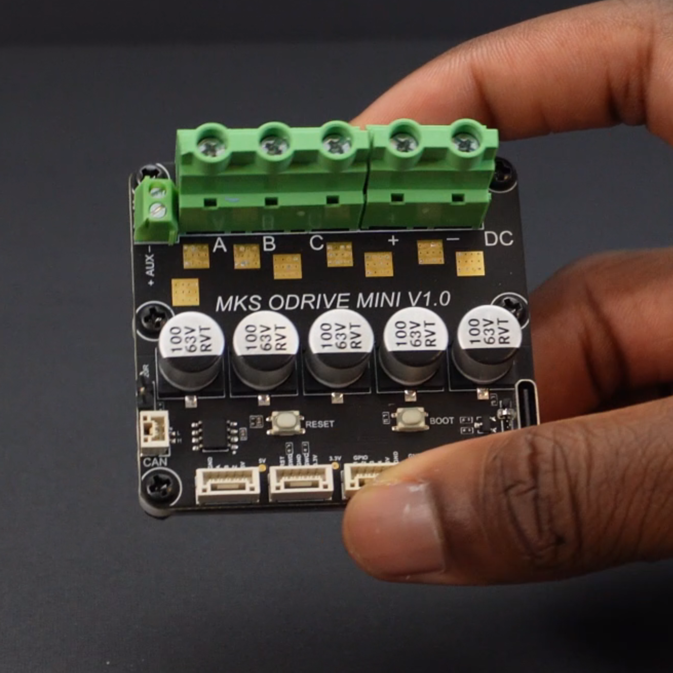
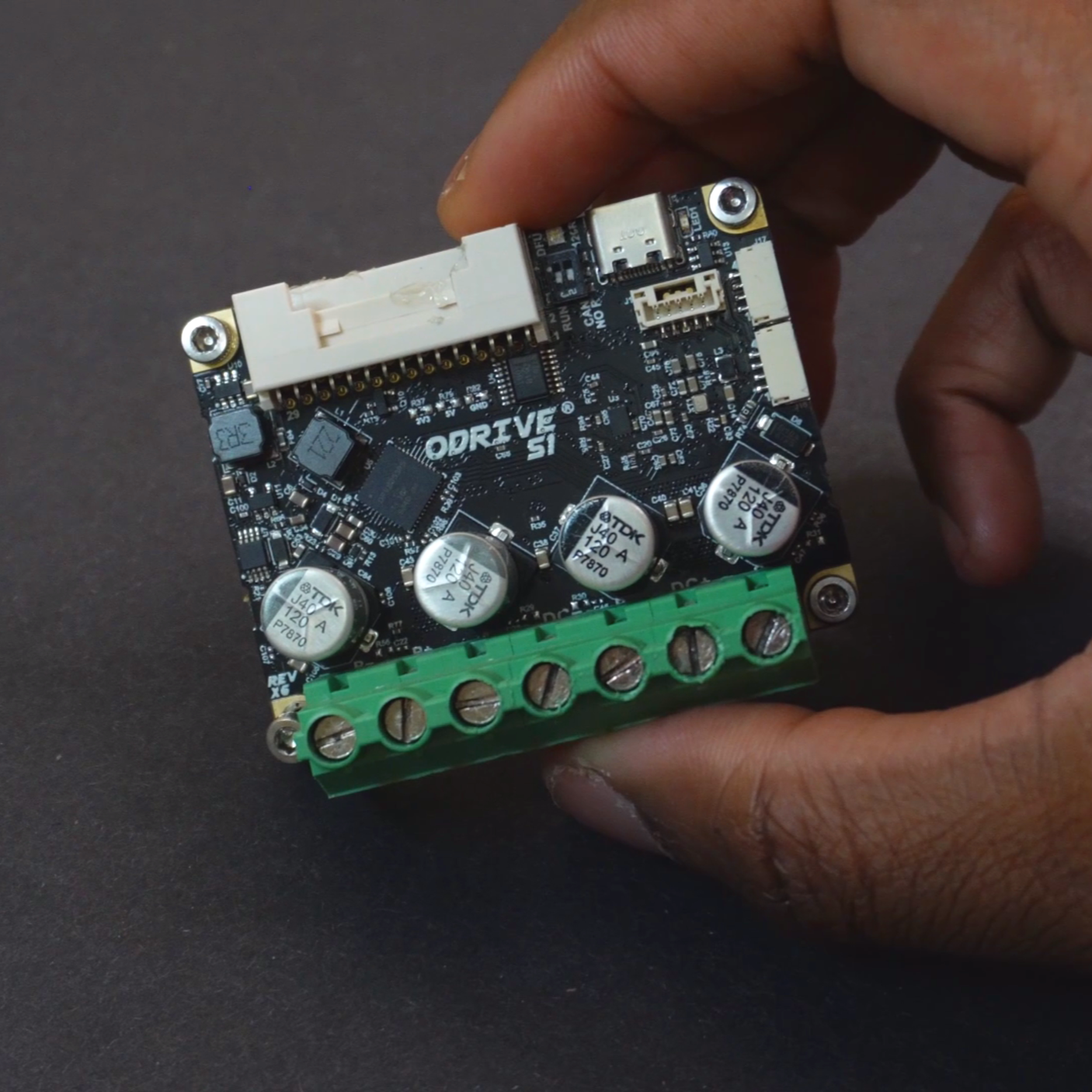
MKS XDrive Mini FOC Controller
Cost: $41
Size (L x W x H): 63 × 58 × 27.8 mm
Weight: 66 g
Input voltage: 12 - 56 V
Continuous current: 60 A
Peak current: 120 A
Onboard encoder: yes
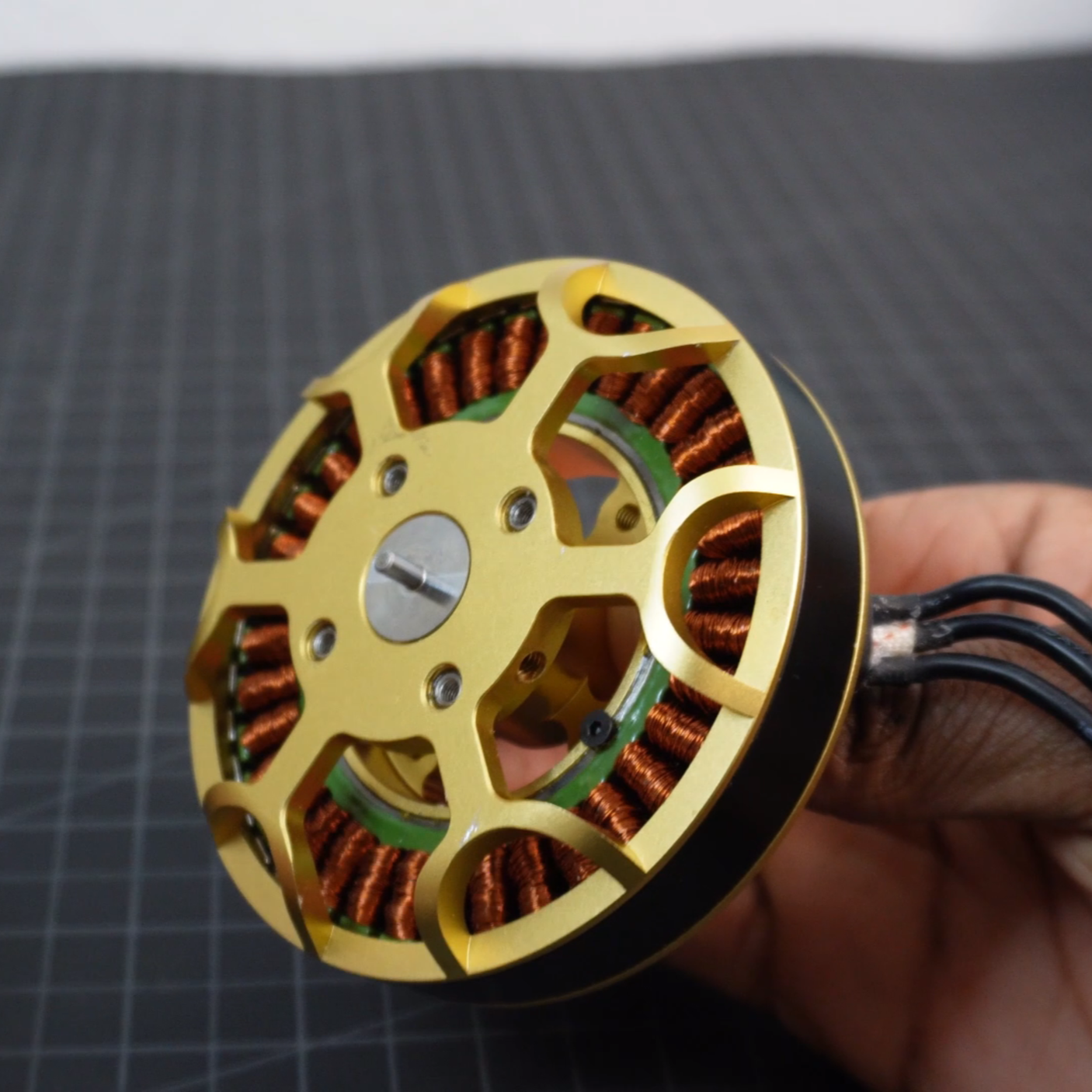
The TYI 5008 is a dirt-cheap Chinese BLDC motor, which is only about ¼ of the cost of the Eagle Power motor used in CARA 1.0. I don’t think it’s possible to find motors that are this cheap yet powerful enough to use for robotics. They’re also surprisingly high quality as they use arced magnets and balancing glue. The XDrive controllers are perhaps an even better bang for your buck. They’re also about ¼ of the price of the ODrive S1 controllers used in CARA 1.0, but they’re actually rated for higher voltage and current! This almost seemed too good to be true, and as I found out, it was. While this pair of actuation hardware was extremely cheap, it came with some drawbacks.
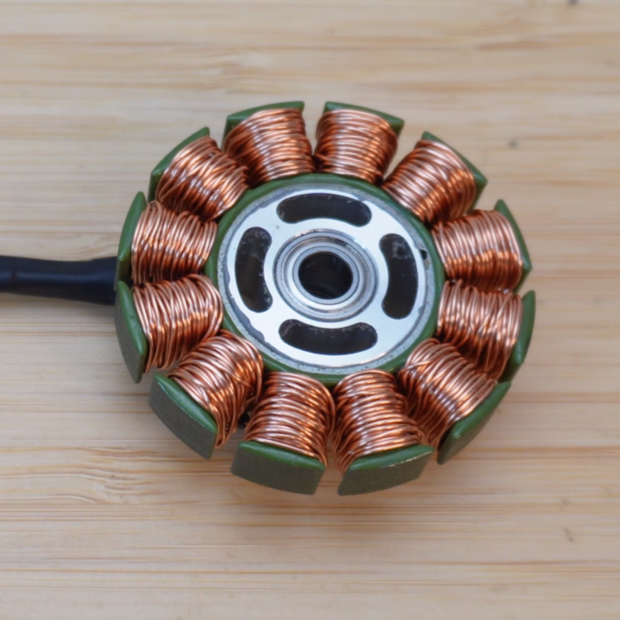
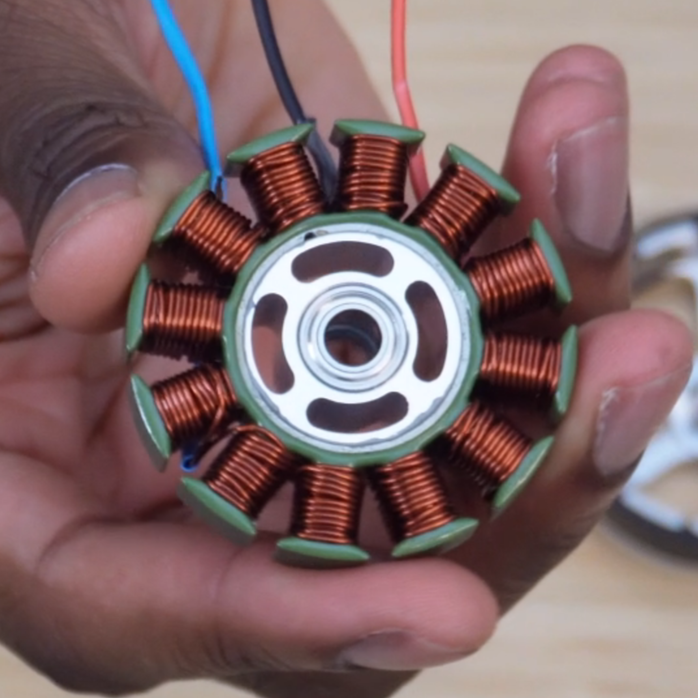
Rewinding Motors, an Arthtitis Speedrun
The one flaw of the TYI motors is that it has a really high KV i.e., a really low Kt or torque per amp rating. The simplest way to fix this issue would be to use a high gear reduction gearbox in the actuator, but as mentioned before, a QDD actuator needs a low reduction. So, we decided to modify the motors themselves by rewinding them to reduce their KV rating and thus increase their torque per amp rating. The idea of rewinding the motors came to me as I inspected the motors’ windings. They seem to have so much space for more magnet wire. I’m guessing that since these motors were designed for drones, a low winding density was favorable as it leads to high KV and thus high speed. Before rewinding the motors, I took one apart to understand how the manufacturer wound them. What I found was that the motors were wired in a delta configuration and wound with 22 turns/slot of a single strand of 22 AWG magnet wire. My goal was to wind the motors down from 335 KV to 100 KV, which is a good KV rating for a high torque actuator. Firstly, I knew that I would have to wire the motor using star configuration, since it provides more torque at low speeds than delta. Specifically, delta wiring has a √3x higher KV than an identically wound motor wired in star. Secondly, I knew I was going to have to use a single strand of 24 AWG magnet wire for a couple of reasons. Any lower gauge would be too thick to pack a substantial amount of wire on the stator. Any higher gauge would require multiple strands in order to have a high current-carrying capacity, which would also limit the number of turns that could be wound on each slot. I came to this conclusion after trying a bunch of different winding gauges and strand numbers on a mock stator. In the end, a single strand of 24 AWG wire seemed to be the ideal thickness to pack as much copper on the stator with as many turns per slot. The last and most important question was “how many turns per slot are needed to achieve 90 KV?” Well, a KV rating is directly proportional to the number of turns/slot on a motor. So, using the manufacturer's KV rating, the manufacturer’s turns/slot value, the target KV, and the KV reduction factor from delta to star, you can calculate the target turns per slot as shown below.
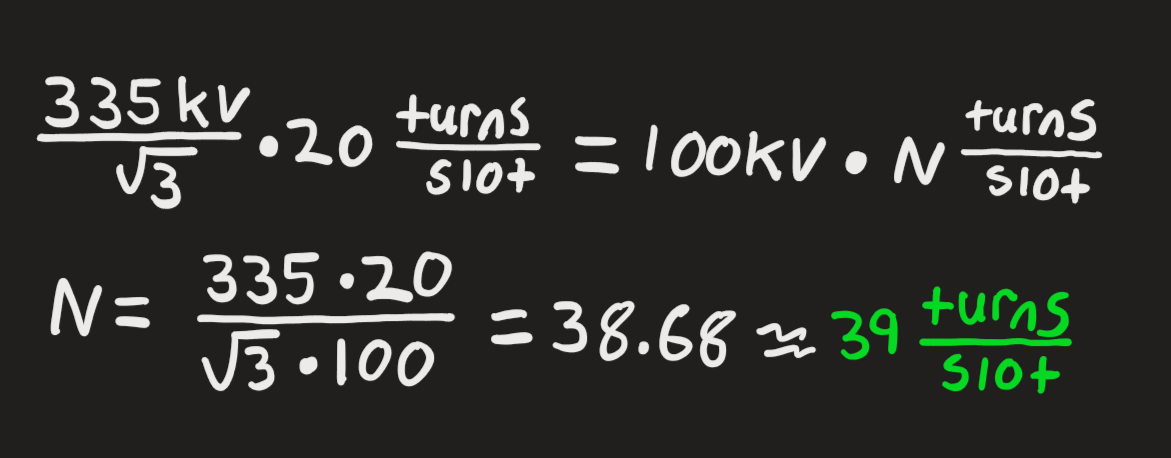
Rewinding Calculations
From the calculations, it’s shown that it takes approximately 39 turns per slot to achieve 100 KV on the TYI motors. I decided to round this up to 40 turns/slot to work with an even number. After rewinding a motor, I conducted KV and torque tests and found the below parameters.
Manufacturer Wound TYI Motor
Rated KV: 335
Weight: 160 g
Measured stall torque: 0.421 Nm
Rewinded TYI Motor
Rated KV: 90
Weight: 160 g
Measured stall torque: 1.274 Nm
I was able to get the KV down to 90, which is even better than what I targeted. This produced a much higher Kt or torque per amp rating. One interesting thing that I noticed was that the weight of the rewinded motor remained the same as the manufacturer-wound motor. This just goes to show that you can radically change the characteristics of a motor without adding or removing the amount of copper.
When Cheap Motor Controllers Don’t Work
The XDrive Mini controllers are one of the cheapest and most powerful FOC controllers that can be purchased off the shelf, but that means they come with a ton of issues. I knew this going in, but it didn’t make the troubleshooting any less torturous. When you pay $150 for an ODrive S1, you aren’t just paying for the physical hardware; you’re paying for the UI, the documentation, and the continued support that it comes with. With cheaper alternatives, you don’t get any of that!
The XDrives are single-axis ODrive 3.6 clones that look like the ODrive S1. The main issue with the XDrives is communication. They work perfectly fine with UART but not with CAN bus. UART sucks for making high DoF robots because MCUs only have so many UART ports. The Teensy 4.1 MCU that I used for this project, and most of my other robotics projects, only has 8 UART ports, so I would only be able to control 8 motors instead of 12. CAN bus is a much more preferred comms protocol for robotics. The boards come with a custom firmware made by the manufacturer called 0.5.1. After running some test CAN bus code on the boards, it seemed to be able to send commands to the motor, but it couldn’t provide encoder or current feedback, which are critical for a highly robust and dynamic robot. I then turned to using ODrive’s Open Source Firmware. This firmware did provide encoder and current feedback, but it wasn’t able to maintain stable communication with the motors. This issue was particularly annoying as it varied every time. Sometimes the motor would run for a minute and then disconnect, sometimes for an hour, and sometimes for 30 seconds. I tried a bunch of different things to isolate any variables that may be at play here. I tried changing the loop frequency, decongesting the bus by slowing down heartbeats and message rates, and using pretty much every open-source firmware version that ODrive provided. Nothing worked, and it became clear that I was missing something. So, I decided to do some digging online to see if anyone else had experienced this issue, and I came across Mohammad Marshid, who created a custom version of the XDrive’s 0.5.1 firmware that could send encoder feedback (Mohammad’s firmware). I reached out to Mohammad to see if he could also add current feedback to the firmware, and luckily, he was able to do so! Big shout-out to Mohammad! With the new firmware, I was able to maintain stable communication with the motor and also get motor feedback. So, it seems like boards will only work with their native firmware.
Alas, a Capstan Drive Joint Test Stand!
With the motor rewinded for more torque and the motor controller comms issues sorted out, it only made sense to prototype a single capstan drive joint test stand. The design of the drive is pretty similar to my previous capstan drive designs. A small drum rotates a big drum through a tensioned rope that’s wrapped around both drums. The drive weighs 470 g (1 lb), features a 9.6:1 reduction, produces 12 Nm of peak torque, and has a range of motion (ROM) of 120°. One thing that I’ve come to realize over the course of making capstan drives (especially from YouTube comments) is that trying to achieve an exact reduction is a fruitless effort. I’ve spent an incredible amount of time trying to derive equations to properly determine the exact drum diameters needed to achieve certain ratios, but they never work across the board. The best way to make a capstan drive is to have a target ratio in mind, estimate the target effective drum diameters using a bit of math, and then measure and calculate the gear reduction (Δoutput shaft position/Δmotor shaft position). As always, the drive used Dyneema DM20 rope, which is the lowest creep rope that money can buy. Specifically, I used 1mm Mastrant-M Rope, which is double braided, abrasion resistant, and has a strength of 100 kg (225 lbs) with a working load of 30 kg (66 lb). One thing I’ve added to the capstan drive assembly process with this project is prestretching the rope. I found that this helps get rid of slack, thus limiting the amount of tensioning needed when the rope is installed on the drive. In total, the single joint costs around $80 to make, which is a bit higher than the target range, but still quite affordable.
Single Leg Design - The Easy Part
Naturally, after building a single joint, it only makes sense to design a single leg. From CARA 1.0, I knew that a coaxial 5-bar linkage design would be the most ideal design since it allows for less loading on each link compared to a standard quadruped leg. I also love the fact that most quads don’t use this design, making CARA super unique. Also, a coaxial 5-bar linkage pairs super well with a capstan drive. In fact, I believe it’s the most compact way to create a 3-DOF leg with a capstan drive. Since we already knew what the leg would look like, the design process became an optimization problem. How can we improve cost, weight, and assembly?
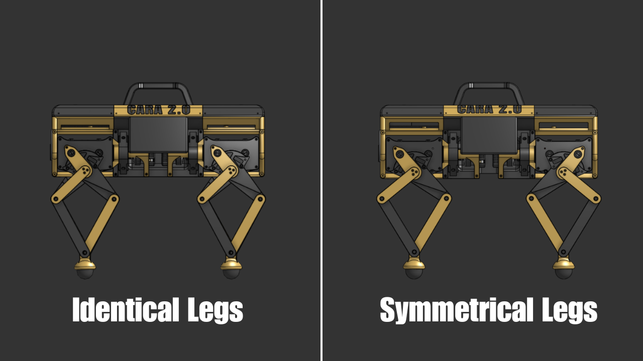
The first thing we decided to improve was the number of mirrored parts in the leg. CARA 1.0 used a ton of mirrored parts, which made assembly confusing at times. This time, we decided to make each leg on the bot identical. Ultimately, this bit us in the back, but more on that later. We also decided to reduce the number of screws used in the leg. Why use 4 screws to fasten something that just needs 2? I’ve started asking myself more questions like this since screws add cost, weight, and assembly time to builds. In line with screws, we also got rid of redundant bracing on some parts. Overconstraining a part doesn’t immediately seem like an issue, but it definitely can become one since things in the real world are never perfect. One good example is 4 legged table. You only need 3 legs to fully constrain a table. That 4th leg overconstrains the table. So, if one leg happens to be a little shorter or taller than the others, the whole table becomes unbalanced. To help further reduce weight, we also used much thinner bearings. There are a lot of radially constrained parts in the leg, so lighter bearings go a long way in making the robot itself significantly lighter. The total weight of the single leg was 1.47 kg (3.24 lbs).
One thing I wanted to investigate with CARA 2.0’s leg design was the upper-to-lower link ratio of the 5-bar linkage. For CARA 1.0, I used a 1:2 ratio just on a whim without doing any analysis. This time, I had one of my teammates investigate the ideal ratio using a MATLAB simulation. What we found was that a 1:1 ratio gives you the highest ROM. Unfortunately, a 1:1 ratio looks kinda goofy, so we ended up using a 2:3 ratio to get a bit more ROM while preserving aesthetics. Lastly, the biggest performance change we made with the leg design was switching from a TPU foot to a squash ball foot. TPU feet sucked with CARA 1.0 as it’s simply a flexible plastic with no compliance or traction. Squash balls, on the other hand, excel in compliance and traction. Squash balls are also super cheap and were used in the MIT Mini Cheetah as well as Stanley, both high-performing quads. There are actually 4 main types of squash balls: blue dot (beginner), red dot (progressing), single yellow dot (competition), and double yellow dot (pro). Double yellow dot is the firmest and least bouncy, so we chose those.
Because the squash ball foot could not be placed at the center of the 5-bar linkage pivot (like the TPU foot), new inverse kinematics (IK) equations had to be derived. You can view those derivations as well as the forward kinematics equations (FK) here. A question I often get asked is “how do you learn to derive IK equations?” While it may look difficult, it’s not. It’s just very tedious with lots of room to make mistakes. I’ve never used more than 8th-grade geometry to derive IK or FK equations. Any complex robot structure can be broken up into a series of triangles. I’ve only ever used James Bruton’s video on IK to learn how to derive kinematics equations (How Robots Use Maths to Move). Once you know the working principle behind it, you can basically derive IK and FK equations for any robot, given that you’re proficient in geometry.
CARA 1.0 Leg Design
CARA 2.0 Leg Design
All Together Now
Robot Design
With a single leg designed, we moved on to the full robot design. From CARA 1.0, I had a bunch of things I wanted to change. Firstly, CARA 1.0 had the electronics separated in a front and back compartment. This was a horrible design choice. It meant that I had to use long lengths of wires to connect components from the front and back of the robot. For CARA 2.0, we decided to go with an electronic box (e-box) on top of the robot. This made it a lot easier to wire the electronics. The e-box also allowed us to position the battery in the center of the robot to balance out its weight. One aesthetic design choice I hated about CARA 1.0 was how wide she was. A lot of the comments said she looked like a pug or a cow. I personally hate pugs, so I took this personally. Moving the electronics from the middle of the bot to the top helped a lot with making CARA look less wide. CARA 1.0’s frame was made up of carbon fiber tubes, which worked well but were quite expensive. To bypass this cost, I decided to design 3D printed structures for CARA’s frame. This seems like a no-brainer, but it’s not something I would have thought about if not for the cost constraint. CARA 1.0 weighed in at 31.41 lbs (14.25 kg) and measured 24.82 × 17.98 × 16.83 in (630.55 × 456.81 × 427.51 mm). CARA 2.0 weighed in at 18.2 lbs (8.26 kg) and measured 20.51 x 13.88 x 16.75 in (521 x 353 x 425 mm). CARA 2.0 was printed entirely out of PLA on my Bambu Lab A1 and X1C, as well as on one of my teammates’ Bambu Lab A1s.
CARA 1.0 Design
CARA 2.0 Design
The electronics schematic of CARA 2.0 is shown below. I’m always shockingly impressed by how simple the schematic of a quad is. All electronics can be bought off the shelf and can be assembled on a protoboard. No custom PCBs required! You can find links to all the electronics used in the BOM.
One important discovery I made while working on this project was the proper wiring of CAN bus. As implied by the name, CAN devices must be wired in a bus where each device (except for the last one) is connected to a previous device and a following device, as shown in the schematic. In addition to this, both ends of the bus must have a 120 Ω resistor connected between the CAN H and CAN L lines, which creates a total of 60 Ω of resistance between CAN H and CAN L. The image shows only one of these 120 Ω resistors since the CAN transceiver we used already had a 120 Ω resistor onboard. Prior to this project, I neither wired my devices in a bus nor added a 120 Ω resistor on the end. Though I never encountered any problems doing this, it’s always best practice to wire things correctly. Robotics is notorious for ghost issues, so minimizing potential failure points is key.
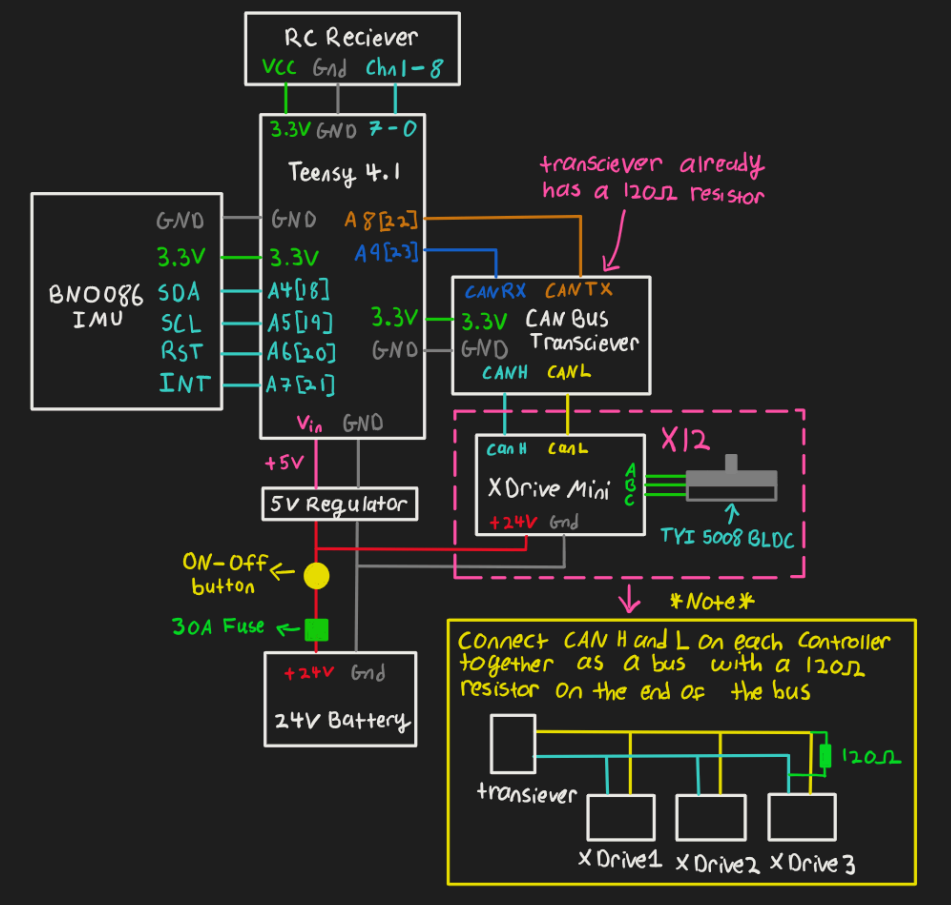
CARA 2.0 Electronics Schematic
Programming Gait
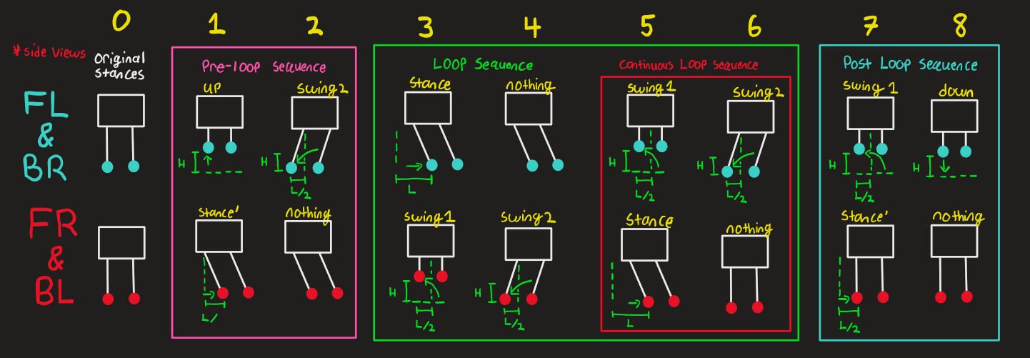
The robot uses a trotting sequence where diagonal legs take a step at the same time. This way, there’s always at least 2 legs on the ground to maintain stability. The gait sequencing occurs as shown below. The example sequence shown is for when the robot is walking forward, but the same pattern applies when the robot walks in any direction. Two important terms to know when it comes to gait are swing phase and stance phase. The swing phase is when the foot travels off the ground, and the stance phase is when the foot moves on the ground, pushing the robot. There are 4 sections in the gait sequence. When the robot receives a walking command, it enters the pre-loop sequence, where it gets the legs in position to enter the loop sequence. The loop sequence runs continuously until the robot receives a command to stop walking. Within the loop sequence is another section called the continuous loop sequence. This sequence will always run unless the robot has received a command to stop walking. After exiting the loop, the robot enters the post-loop sequence to terminate the current step that it had embarked on in the loop. The step trajectory is a cycloid. I experimented with different step trajectories with CARA 1.0, and a cycloid came out on top as being the most natural-looking step trajectory. In the diagram, FL, BR, FR, and BL refer to the Front Left, Back Right, Front Right, and Back Left legs, respectively.
Gait Sequence
A Glaring Design Issue
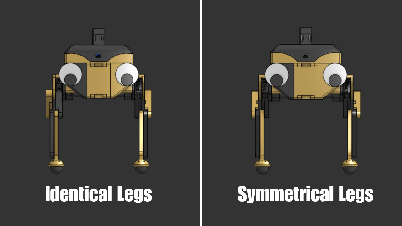
After programming the gait sequence and getting some initial walking tests done, there was a clear issue with CARA’s gait. Every time we tried to make her walk straight, she would turn left. This was such an odd issue because I had never experienced it with CARA 1.0. We tried programming the legs on either side of the robot to take different step lengths, but the problem still persisted. After doing some root cause analysis with the team, the issue eventually became clear. if you remember, we had designed CARA 2.0’s legs to be identical to make assembly easy, but this meant that the legs on either side weren’t symmetrical. Something that you may not immediately notice about the leg design is that the feet never actually point straight down. They’re always slightly angled. So when the left and right legs are identical, it creates an imbalance on each side, thus creating a bias in the robot’s gait. Imagine that your left leg was pointed backwards instead of forward. It would probably be harder for you to walk in a straight line. You would also be hilariously easy to knock over. To fix this gait bias issue, we redesigned the front and back legs as well as the left and right legs to be symmetrical. I should also note that if you used reinforcement learning to teach the robot how to walk, you could actually train it to walk straight with asymmetrical legs. Disney’s Olaf robot does exactly that. I’d still argue that it’s best to design your robot to be as balanced as possible. In the case of the Olaf robot, space constraints necessitated the asymmetrical design.
Fixing Turning
I didn’t realize it at the time, but CARA 1.0 turned incredibly slow. I had a follower reach out and explain to me that turning was slow because I programmed CARA to turn by stepping directly to the side instead of stepping at a 45° angle. In retrospect, this makes sense. When turning, the robot is essentially pivoting on a circle; thus, each foot should step in a direction that is tangent to the circle.

CARA 1.0 Bad Turning
CARA 2.0 Good Turning
Fixing Dynamic Stability
Another issue with CARA 1.0 was dynamic stability. With an IMU onboard, I wrote code for the robot to turn an equal and opposite angle to incline it was on. In my mind, this would allow the robot to stay level on any surface. When you watch a video of this dynamic stability method implemented in the robot, it doesn’t work. In fact, if you think about the method for a couple of seconds, you realize the problem. Imagine the robot is on a 20° incline, so the IMU measures 20°. If the robot then rotates -20°, then the IMU now measures 0°, which means the robot rotates back to 0° and the cycle continues. In real life, the robot never really moved using this method. I didn’t realize this until after posting the CARA 1.0 video and seeing some comments about it. The better way to go about dynamic stability is to have the robot shift its center of mass so that it stays right between its legs. We humans naturally do this when we walk on inclines. For example, if you walk up a hill, you’ll naturally lean forward so that you don’t fall backwards. A bit of trigonometry was used to determine how the robot needs to shift its center of mass to have it stay between its legs. You can view those derivations here.
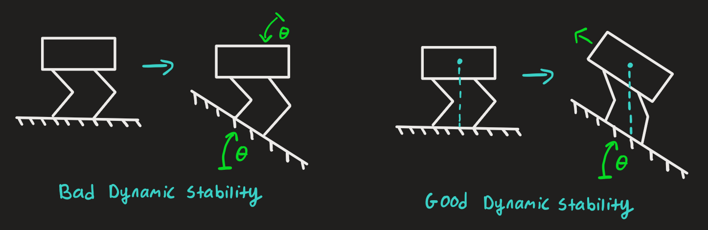
CARA 1.0 Bad Dynamic Stability
CARA 2.0 Good Dynamic Stability
Epilogue
CARA 2.0 Specs
Cost: $1,450
Weight: 18.2lbs (8.26 kg)
L x W x H (standing): 20.51 x 13.88 x 16.75 in (521 x 353 x 425 mm)
Walking speed: 1.8 ft/s (0.55 m/s)
Payload capacity: 15 lbs (6.8 kg)
Battery voltage: 24 V
Battery capacity: 3 Ah
Runtime: 1 hr
Overall, I would call this project a success. We were able to slash the cost of CARA 1.0 in half while retaining dynamic functionality and even improving in a lot of areas. While we didn’t quite hit the $1,000 price goal, $1,450 for a quadrupedal robot is still really good. I don’t think it’s an understatement to say that CARA 2.0 is one of the cheapest and most dynamic quadrupedal robots that can be made on a hobbyist level. Be that as it may, there are still a lot of things that we couldn’t quite get to with the project. The main one is proper walking via reinforcement learning. Gone are the days when you manually program gait sequences for robots. Now, everything is trained in simulation and deployed onto hardware. I thought about doing this with CARA, but I’m officially retiring this project to work on other things. I plan on making more quads in the future, but when I do, they almost certainly won’t use capstan drives. Why? Well, capstan drives just aren’t very assembly-friendly. They excel in a lot of areas, but they require a high level of precision to build. I often get asked, “Why aren’t capstan drives used in industry?“ and this is why. When it comes to capstan drives, I’ve been there and done that. Moving forward, I’ll be using off-the-shelf actuators to build my robots.